How to Wire a Resistor and What is Its Working Principle?
I. Introduction
Resistors are fundamental components in electrical circuits, playing a crucial role in controlling the flow of electric current. They are used in a variety of applications, from simple household electronics to complex industrial machinery. Understanding how to wire a resistor and grasping its working principles is essential for anyone interested in electronics, whether you're a hobbyist or a professional engineer. This article aims to provide a comprehensive guide on resistors, their functions, and how to wire them effectively.
II. Understanding Resistors
A. What is a Resistor?
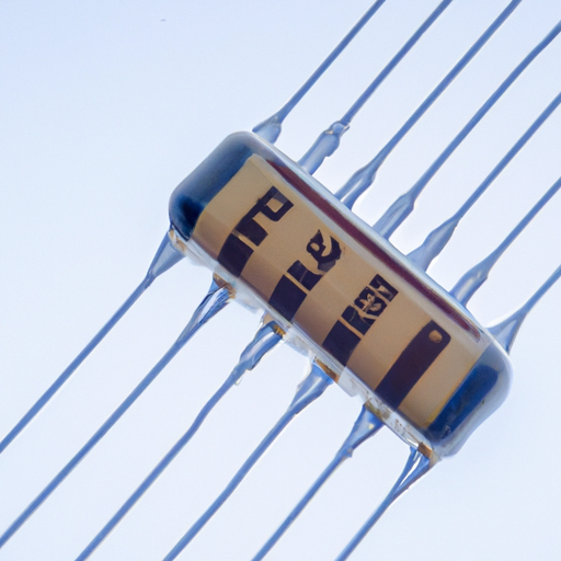
A resistor is a passive electrical component that limits or regulates the flow of electrical current in a circuit. It is characterized by its resistance value, measured in ohms (Ω). Resistors come in various types, including:
1. **Fixed Resistors**: These have a constant resistance value and are the most common type used in circuits.
2. **Variable Resistors**: Also known as potentiometers or rheostats, these allow the resistance to be adjusted, making them useful for applications like volume controls in audio equipment.
B. The Role of Resistors in Circuits
Resistors serve several critical functions in electrical circuits:
1. **Current Limiting**: By restricting the flow of current, resistors protect sensitive components from damage due to excessive current.
2. **Voltage Division**: Resistors can be used to create a specific voltage level within a circuit, which is essential for powering different components that require varying voltage levels.
3. **Signal Conditioning**: In signal processing applications, resistors help shape and filter signals, ensuring that they meet the required specifications for further processing.
C. Key Specifications of Resistors
When selecting a resistor for a specific application, it's essential to consider the following specifications:
1. **Resistance Value (Ohms)**: This indicates how much the resistor opposes the flow of current. The value is often color-coded on the resistor body.
2. **Power Rating (Watts)**: This specifies the maximum amount of power the resistor can dissipate without overheating. Common ratings include 1/4W, 1/2W, and 1W.
3. **Tolerance**: This indicates the accuracy of the resistor's resistance value, expressed as a percentage. A lower tolerance means a more precise resistor.
III. Working Principle of Resistors
A. Ohm's Law
Ohm's Law is a fundamental principle that describes the relationship between voltage (V), current (I), and resistance (R) in an electrical circuit. The formula is expressed as:
\[ V = I \times R \]
This equation shows that the voltage across a resistor is directly proportional to the current flowing through it and the resistance value. Understanding this relationship is crucial for designing and analyzing circuits.
B. How Resistors Dissipate Energy
Resistors convert electrical energy into heat as current flows through them. This process is known as power dissipation, and it can be calculated using the formula:
\[ P = I^2 \times R \]
Where P is the power in watts, I is the current in amperes, and R is the resistance in ohms. It's important to ensure that the resistor's power rating is not exceeded to prevent overheating and potential failure.
C. Temperature Coefficient and Its Effects
The temperature coefficient of a resistor indicates how its resistance changes with temperature. Most resistors have a positive temperature coefficient, meaning their resistance increases as temperature rises. This characteristic is crucial in applications where temperature fluctuations are expected, as it can affect circuit performance.
IV. Wiring a Resistor
A. Tools and Materials Needed
Before wiring a resistor, gather the following tools and materials:
1. **Resistors**: Choose the appropriate type and value for your circuit.
2. **Breadboard or PCB**: A breadboard is ideal for prototyping, while a printed circuit board (PCB) is used for permanent installations.
3. **Soldering Iron**: If you're using a PCB, a soldering iron will be necessary to make secure connections.
4. **Multimeter**: This tool is essential for measuring resistance, voltage, and current in your circuit.
B. Step-by-Step Guide to Wiring a Resistor
1. **Identifying Resistor Leads**: Resistors typically have two leads. The longer lead is usually the positive side, while the shorter lead is the negative side. However, for fixed resistors, polarity does not matter.
2. **Connecting Resistors in Series**: To connect resistors in series, simply connect one lead of the first resistor to one lead of the second resistor. The total resistance in a series circuit is the sum of the individual resistances:
\[ R_{total} = R_1 + R_2 + ... + R_n \]
3. **Connecting Resistors in Parallel**: For parallel connections, connect all the resistor leads together at one end and all the other leads together at the other end. The total resistance in a parallel circuit can be calculated using the formula:
\[ \frac{1}{R_{total}} = \frac{1}{R_1} + \frac{1}{R_2} + ... + \frac{1}{R_n} \]
4. **Using Resistors in a Circuit (Example Circuit)**: Consider a simple circuit with a battery, a resistor, and an LED. Connect the positive terminal of the battery to one lead of the resistor, and connect the other lead of the resistor to the anode of the LED. Connect the cathode of the LED back to the negative terminal of the battery. This setup limits the current flowing through the LED, preventing it from burning out.
C. Common Mistakes to Avoid
1. **Incorrect Resistor Values**: Always double-check the resistor value before installation. Using the wrong value can lead to circuit malfunction or component damage.
2. **Overheating and Power Ratings**: Ensure that the resistor's power rating is suitable for the application. If the resistor gets too hot, it may fail or cause damage to surrounding components.
3. **Misconnections in Series and Parallel**: Be cautious when connecting resistors in series or parallel. Misconnections can lead to incorrect resistance values and circuit behavior.
V. Practical Applications of Resistors
A. Resistors in Everyday Electronics
Resistors are ubiquitous in consumer electronics, such as televisions, radios, and computers. They help regulate current and voltage levels, ensuring that devices operate safely and efficiently.
B. Resistors in Specialized Applications
In specialized applications, resistors play a vital role in signal processing and voltage regulation. For example, in audio equipment, resistors are used to adjust signal levels and prevent distortion.
C. Future Trends in Resistor Technology
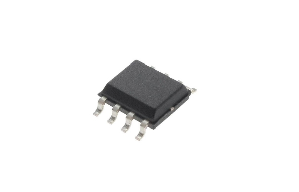
As technology advances, new materials and designs for resistors are being developed. Innovations such as thin-film resistors and surface-mount technology (SMT) are becoming increasingly popular, offering improved performance and miniaturization for modern electronic devices.
VI. Conclusion
Resistors are essential components in electrical circuits, serving various functions that are critical for the proper operation of electronic devices. Understanding how to wire a resistor and the principles behind its operation is fundamental for anyone interested in electronics. By following the guidelines outlined in this article, you can confidently work with resistors in your projects and experiments. We encourage you to explore further and experiment with different resistor configurations to deepen your understanding of electronics.
VII. References
A. Suggested readings and resources for further learning:
- "The Art of Electronics" by Paul Horowitz and Winfield Hill
- "Make: Electronics" by Charles Platt
B. Online tutorials and courses on electronics and circuit design:
- Coursera: Electronics Courses
- Khan Academy: Electrical Engineering
By delving into these resources, you can expand your knowledge and skills in electronics, paving the way for exciting projects and innovations.


