How Does a Resistor Wiring Diagram Work?
I. Introduction
In the world of electronics, resistors play a crucial role in controlling the flow of electric current. A resistor is a passive electrical component that limits or regulates the flow of electrical current in a circuit. Understanding how resistors function and how they are represented in wiring diagrams is essential for anyone interested in electronics, whether you're a hobbyist, a student, or a professional engineer. This blog post will explore the workings of resistor wiring diagrams, their components, and their practical applications.
II. Understanding Resistors
A. What is a Resistor?
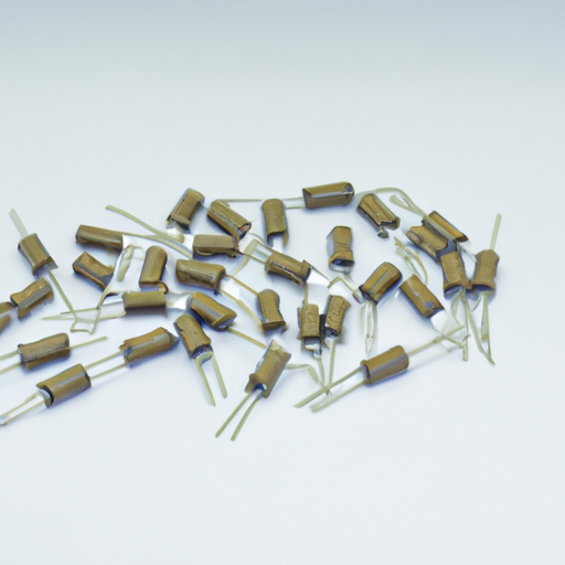
1. **Function and Purpose**: Resistors are used to manage the flow of current in a circuit. They can protect sensitive components from excessive current, divide voltages, and set bias points for transistors. By providing resistance, they help ensure that circuits operate within safe limits.
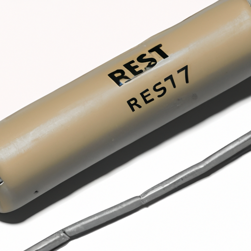
2. **Types of Resistors**: There are various types of resistors, including fixed resistors, which have a constant resistance value, and variable resistors, such as potentiometers, which allow for adjustable resistance. Other types include thermistors, which change resistance with temperature, and photoresistors, which change resistance based on light exposure.
B. Basic Principles of Resistance
1. **Ohm's Law**: The relationship between voltage (V), current (I), and resistance (R) is defined by Ohm's Law, which states that V = I × R. This fundamental principle is essential for understanding how resistors function in a circuit.
2. **Units of Measurement**: Resistance is measured in ohms (Ω), while power is measured in watts (W). Understanding these units is crucial for calculating how resistors will behave in different circuit configurations.
III. Components of a Resistor Wiring Diagram
A. Symbols Used in Wiring Diagrams
1. **Resistor Symbol**: In wiring diagrams, resistors are typically represented by a zigzag line or a rectangle. This symbol helps differentiate them from other components in the circuit.
2. **Other Relevant Symbols**: A complete wiring diagram will also include symbols for other components, such as voltage sources (batteries), ground connections, and switches. Familiarity with these symbols is essential for interpreting diagrams accurately.
B. Layout of a Typical Wiring Diagram
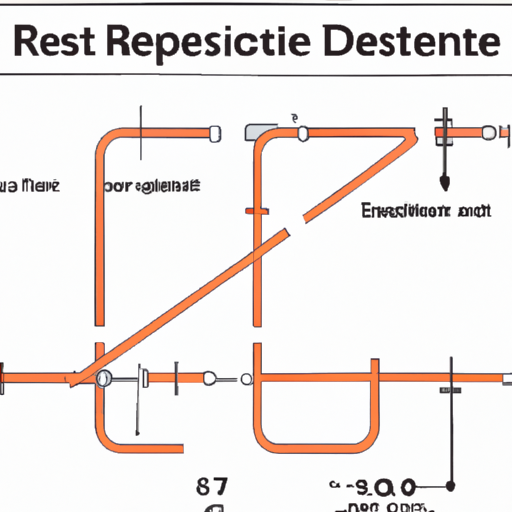
1. **Circuit Representation**: A wiring diagram visually represents the electrical connections and layout of a circuit. It shows how components are connected and the path that current will take.
2. **Connections and Nodes**: Nodes are points in the circuit where two or more components connect. Understanding how to identify these connections is crucial for analyzing and troubleshooting circuits.
IV. How to Read a Resistor Wiring Diagram
A. Step-by-Step Guide to Interpreting Diagrams
1. **Identifying Components**: Start by identifying all the components in the diagram. Look for the resistor symbols and note their values, which may be indicated next to the symbol.
2. **Understanding Connections**: Follow the lines connecting the components to understand how they are wired together. Pay attention to the direction of current flow, which is typically indicated by arrows.
B. Common Mistakes to Avoid
1. **Misreading Symbols**: One common mistake is misinterpreting the symbols used in the diagram. Ensure you are familiar with the standard symbols to avoid confusion.
2. **Ignoring Circuit Flow**: Another mistake is neglecting the direction of current flow. Understanding how current moves through the circuit is essential for troubleshooting and analysis.
V. Practical Applications of Resistor Wiring Diagrams
A. Circuit Design and Analysis
1. **Designing Circuits with Resistors**: Resistor wiring diagrams are invaluable for designing circuits. They allow engineers to visualize how components will interact and ensure that the circuit will function as intended.
2. **Analyzing Existing Circuits**: When troubleshooting or analyzing existing circuits, wiring diagrams provide a roadmap for understanding how the circuit is constructed and where potential issues may arise.
B. Troubleshooting Electrical Issues
1. **Identifying Faulty Components**: If a circuit is not functioning correctly, a wiring diagram can help identify which components may be faulty. By following the connections, you can isolate the problem area.
2. **Using Diagrams for Repairs**: Once the issue is identified, the wiring diagram can guide repairs. Knowing how components are connected allows for efficient and accurate fixes.
VI. Creating Your Own Resistor Wiring Diagram
A. Tools and Software for Diagram Creation
Creating your own resistor wiring diagram can be done using various tools and software. Programs like Fritzing, Eagle, and KiCad offer user-friendly interfaces for designing circuits. Additionally, online platforms like CircuitLab provide easy-to-use tools for creating and simulating circuits.
B. Steps to Design a Resistor Wiring Diagram
1. **Planning the Circuit**: Before drawing, plan out the circuit on paper. Determine which components you will use and how they will be connected.
2. **Drawing the Diagram**: Use your chosen software to create the diagram. Start by placing the symbols for each component and connecting them with lines to represent the wiring.
3. **Testing the Design**: Once the diagram is complete, simulate the circuit if your software allows it. This step helps ensure that the design works as intended before building the physical circuit.
VII. Conclusion
Resistor wiring diagrams are essential tools for anyone working with electrical circuits. They provide a clear representation of how resistors and other components are connected, making it easier to design, analyze, and troubleshoot circuits. By understanding how to read and create these diagrams, you can enhance your skills in electrical engineering and electronics.
As you explore the world of resistors and wiring diagrams, remember that practice is key. The more you work with these concepts, the more proficient you will become. Whether you're designing a simple circuit for a hobby project or working on complex electronic systems, mastering resistor wiring diagrams will serve you well in your endeavors.
VIII. References
A. Suggested readings and resources for further study:
- "The Art of Electronics" by Paul Horowitz and Winfield Hill
- "Make: Electronics" by Charles Platt
B. Online tools and software for circuit design and analysis:
- Fritzing (fritzing.org)
- Eagle (autodesk.com/products/eagle/overview)
- KiCad (kicad.org)
- CircuitLab (circuitlab.com)
By delving into these resources, you can deepen your understanding of resistors and their role in electrical circuits, paving the way for further exploration in the field of electronics.

